Weidmüller uses gas arresters, varistors or suppressor diodes as components in lightning and surge protection. The electrical elements differ in their response behavior and discharge capacity.
GDT
MOV
TAZ
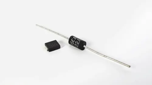
Two electrodes enclose a noble gas (e.g. argon or neon), whereby the electrodes in the gas discharge chamber are coated with an activating compound. There are also gas traps that have an additional ignition aid.
As soon as a voltage is applied between the two electrodes that corresponds to or is greater than the so-called ignition voltage UZ1, the gas ionizes, the gas discharge tube ignites and the pulse current can flow. This current flows until the voltage between the two electrodes falls below the arc-burning voltage UZ2. However, since mains follow currents occur, these must be controlled.
In normal, non-ignited operation, the gas discharge tube has an extremely high electrical resistance. Only after ignition does it drop to an extremely low value. Due to the high impulse energies that a gas discharge tube can dissipate, it is also referred to as coarse protection.
As it is also leakage current-free, a lightning current arrester consisting of gas arresters may be installed upstream of the electricity meter. The response time of a gas discharge tube is in the microsecond range and is therefore rather slow compared to that of varistors and suppressor diodes.
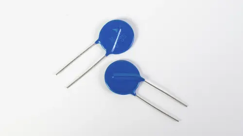
The metal oxide varistors predominantly used today consist of approx. 90% zinc oxide and 10% other metal oxides. The powder is pressed, sintered and contacted with tinned copper wire.
The dimensions can be used to draw conclusions about the technical data. The thickness of the varistor disc, for example, is a measure of the varistor voltage and the diameter of the disc is a measure of the permissible surge current.
A varistor has a symmetrical current-voltage characteristic. As the voltage increases, the resistance of the varistor decreases, giving it a good discharge capacity.
The disadvantage, however, is that varistors are subject to a certain degree of aging. Too frequent or too high-energy discharges cause the diode grains to “alloy through” within the varistor. As a result, the varistor no longer blocks sufficiently in the nominal range and current flows through the component (leakage current).
This leakage current heats the semiconductor layers to such an extent that varistors must also be thermally monitored. For this reason, a pretensioned spring and a soldered connection that melts at a certain temperature are used to safely disconnect the arrester from the mains voltage. The response time of a varistor is faster than that of a gas discharge tube and is in the nanosecond range.
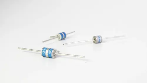
The characteristic curve of the suppressor diode is characterized by the reverse voltage UR, the breakdown voltage UB and the limiting voltage UC.
As soon as the overvoltage is above the breakdown voltage UB, the diode becomes very low-resistance and discharges the current (in the ampere range) to earth. The limiting voltage UC is approximately 1.8 times the nominal voltage and limits the voltage to a value that is safe for the load.
Advantages and disadvantages of the three components gas discharge tube, varistor and suppressor diode
Various components are often combined in lightning and surge protection modules. The components can operate in their optimal working range, which increases the overall efficiency of the SPD. Combination circuits offer fast response, high energy absorption and more effective protection against surge voltages.