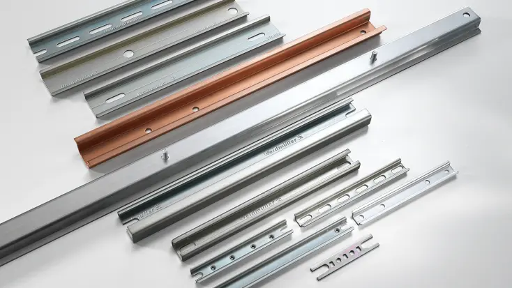
Copper busbars and phase distribution busbars for installation devices

Copper busbars and phase distribution busbars are used for safe and simple cross-connection of miniature circuit breakers, residual current devices and other installation devices in sub-distribution boards and small distribution switchgear. Insulated copper busbars are tested according to the VDE and DIN EN 61439-1 as well as DIN EN 61439-6 and offer finger-safe power supply and distribution of the potential. Additional wiring and cables can be saved thanks to the busbar system. Shortening busbars or cutting / sawing a busbar is generally permitted, as long as a few work steps are observed.

Pin contact or fork contact

Electrical busbars and comb busbars with forked busbars and pin rails for installation on installation devices

The busbar product portfolio includes fork busbar and pin busbar versions with one to four poles. The cross-section and current of the electrical busbars are 10 mm² with 63 A or 16 mm² with 80 A.

Busbar variants with skipping poles are available depending on the installation devices chosen (LS, FI, FI/LS circuit breaker, RCD, RCCB, RCBO) with and without auxiliary contacts. The electrical busbars and busbar system can be shortened or sawed to the required length.

Electrical busbar accessories

Electrical busbars and comb busbars in forked busbar and pin busbar versions with accessories

Accessories for the insulated busbars include feeder modules, end caps and covers. The end caps ensure the required creepage distances in the system even after the busbars have been shortened or cut off and guarantee finger safety in accordance with DIN EN 50274. Various feeder terminals simplify wiring of the cables within the substation.

Product characteristics of our electrical busbars

Standards and regulationsDIN EN 61439-1/ DIN EN 61439-6
Material busbarE-Cu-ETP
Material insulation / end capsPC+ABS
Dimensional stability temperature125°C
Flammability ratingV2
CTI 600 V

Short-circuit resistance Icc25 kA /100 A gl
Dielectric strength36 kV/mm
Rated voltage400 VAC
Rated impulse withstand voltage4 kV
Overvoltage categoryIII
Degree of pollution2

Observe operational leakage currents according to DIN VDE 0701, DIN VDE 0702 and DIN 18015

When constructing a switchgear according to DIN 18015, there is a specification of six current circuits per 3-pole RCD. The specifications of DIN VDE 0701-0702 are described somewhat differently. To prevent undesired switch-off, the operating leakage currents must not exceed 0.3 times the rated residual current of the residual current device.

With a 30 mA version, this would be a maximum of 9 mA. A maximum of six circuits should be provided for a 3-phase RCD (two circuits per phase conductor, each 2×3.5 mA = 7 mA, so that 9 mA is not exceeded).

The copper busbars are designed precisely for this application example. The phases of the residual current device are bridged to the other devices via the neutral conductor connection (N conductor). A rack unit (RU) within the phase distribution bar is skipped to ensure potential sequence.

Downloads on the topic of busbar systems

Consulting & Support